Drive Hardware Description
Overview
BW-DR03 is a high-performance, multi-function, low-cost brushless DC driver with Hall sensor developed by our company. The drive has its own speed closed-loop PID control, the speed control accuracy is within 1%, the low-speed output torque is large, and the high-speed braking is fast. It supports to control two motors at the same time, comes with IMU, and can be connected to 4 infrared obstacle avoidance modules and 2 ultrasonic ranging modules. The speed control and parameter configuration of the driver motor are realized through the rs232 serial port. With the configuration software of the host computer and the ROS driver package, a high-performance robot chassis can be quickly built.
BW-DR03 drive parameter list
| Parameter | Description |
|---|---|
| Motor drive tube input voltage | DC12V-46V |
| Motor Hall Type | 120 degree |
| Working current | 30A Max(15A Single) |
| Operating mode | Hall speed closed loop |
| Speed mode | RS232 serial port commands |
| IMU | MPU9250 with 3-axis accelerometer, 3-axis gyroscope, 3-axis magnetometer |
| Infrared obstacle avoidance module | Support up to 4 channels |
| Ultrasonic ranging module | Maximum support 2 channels |
| working environment | Occasion: no flammable, explosive gas, no dust Temperature: -10-50 degrees Celsius Vibration: less than 0.5G, 10HZ-60HZ Protection level: not waterproof |
| Cooling method | natural air cooling |
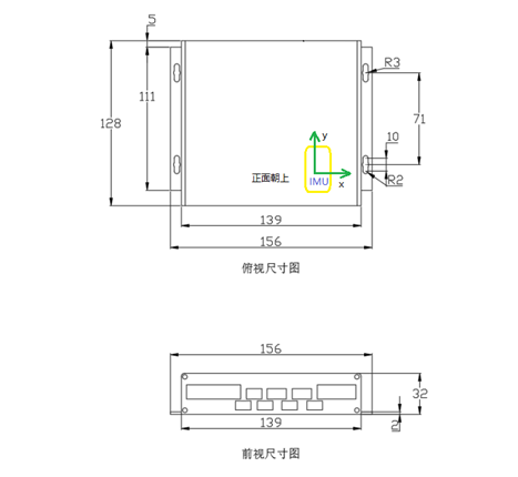
| size | 12815632 |
| weight | 500g |
Features
Speed PID closed-loop control, large torque at low speed.
Wide speed range, 0-2000RPM.
Supports a wide range of motor voltages, 12V-36V.
It supports to control two motors at the same time, comes with IMU, and can be connected to 4 infrared obstacle avoidance modules and 2 ultrasonic ranging modules.
With ROS driver package, you can directly output topic data such as odometer and IMU.
Interface definition
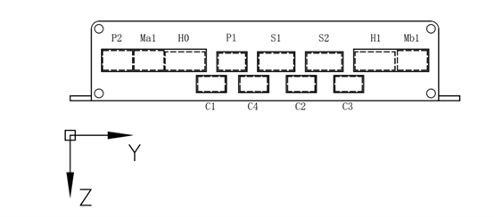
Distribution diagram of the front interface of the drive
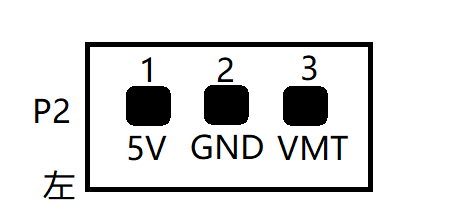
Power input interface P2
| interface | description |
|---|---|
| 1. 5V | RS232 version, this pin is abandoned, please do not connect anything |
| 2. GND | power ground |
| 3. VMT | Motor drive tube power positive input |
The VMT voltage value is determined by the rated voltage of the motor. For example, a 36v motor can be connected to the positive pole of a 36v battery. Note that the battery must be used for direct power supply. Powering it through a dc regulated power supply will burn the driver.
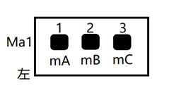
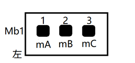
Motor phase line interface Ma1, Mb1
| interface | description |
|---|---|
| 1. mA | Motor phase wire U (yellow) |
| 2. mb | Motor phase line V (green) |
| 3. mC | Motor phase wire W (blue) |
The definition of the color of the motor phase wire is related to the motor manufacturer. When actually wiring, please connect the motor phase wire to mA mB mC at will, and then adjust the Hall phase wire below (in theory, any motor phase wire connection has a set of corresponding Therefore, you can arbitrarily specify the wiring sequence of the motor phase wires). When the driver can normally control the forward and reverse rotation of the motor in the open-loop mode, it means that the wiring sequence of the Hall phase wires and the motor phase wires is correct. For details, please refer to the relevant chapters in the driver configuration software manual.
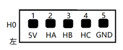
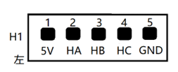
Motor Hall line interface H0, H1
| interface | description |
|---|---|
| 1. 5V | Hall power supply positive |
| 2. HA | Hall U line (yellow) |
| 3. HB | Hall V line (green) |
| 4. HC | Hall W line (blue) |
| 5. GND | Hall power supply ground |
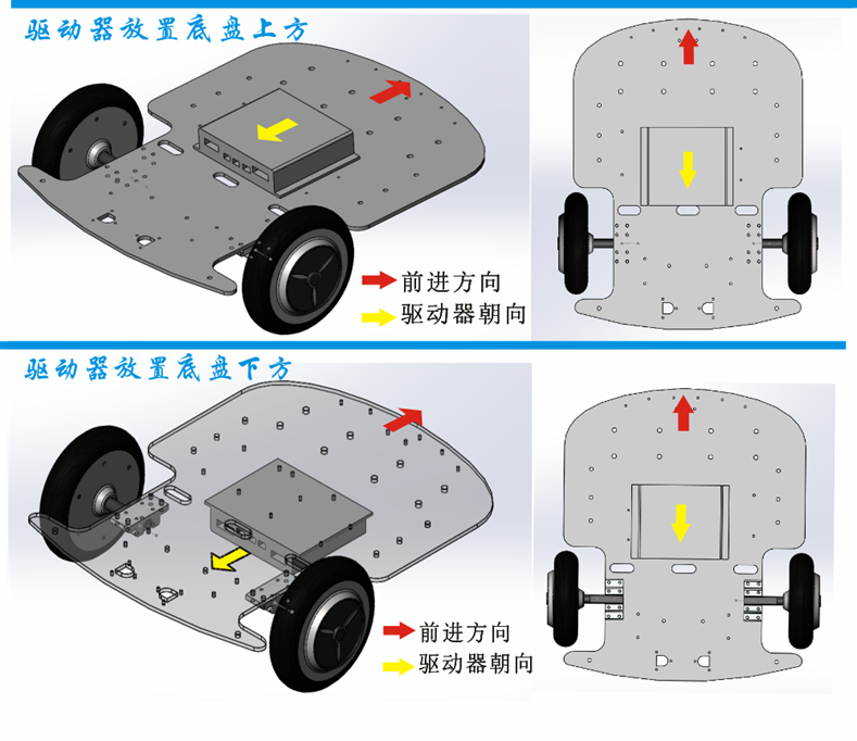
H0 corresponds to Ma1 channel motor, H1 corresponds to Mb1 channel motor When the driver is installed face down, Ma1 corresponds to the right wheel motor, and Mb1 corresponds to the left wheel motor; when the driver is installed face up, Ma1 corresponds to the left wheel motor, and Mb1 corresponds to the right wheel motor.
Infrared obstacle avoidance module interface C1, C4, C2, C3
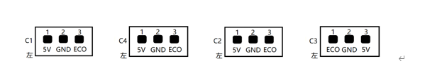
| interface | description |
|---|---|
| 5V | Module power supply positive |
| GND | Module power ground |
| ECHO | module output pin |
Please note that the pin arrangement directions of C3 and C1, C4, and C2 are different. Usually, C1, C4, and C2 are used to detect obstacles in front of the chassis, and C3 is used to detect obstacles behind the chassis. Therefore, the arrangement direction is designed as different. When the module is triggered by an obstacle, the module ECO pin outputs a low level (driver feedback 0), and in other cases the module ECO outputs a high level (driver feedback 1).
Ultrasonic ranging module interface S1, S2
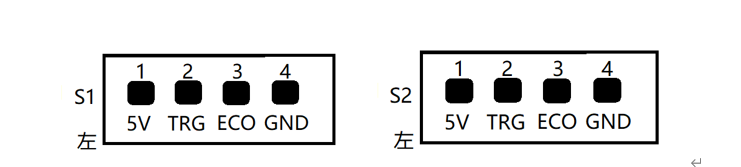
| interface | description |
|---|---|
| 1. 5V | Module power supply positive |
| 2. TRG | Module measurement trigger pin |
| 3. ECO | Module measurement data output pin |
| 4. GND | Module power ground |
This driver supports the serial integrated ultrasonic ranging module, the measurement frequency of the driver is 5hz, and the unit of uploading data is meters.
Serial communication interface P1

| interface | description |
|---|---|
| 1. TXD | Drive serial data upload port |
| 2. RXD | Drive serial command receiving port |
| 3. GND | Serial ground |
The communication connection mode of the driver is RS232 serial port, the serial port baud rate is 115200, 8 data bits, 1 stop bit, no parity check.
communication protocol
The serial port baud rate is 115200, 8 data bits, 1 stop bit, no parity.
computer commands
The direction motion commands are all 6-byte unsigned byte arrays. When the driver is installed face down, Ma1 corresponds to the right wheel motor, and Mb1 corresponds to the left wheel motor; when the driver is installed face up, Ma1 corresponds to the left wheel motor, and Mb1 corresponds to the right wheel motor.
Forward
| 0xcd | 0xeb | 0xd7 | 0x02 | 0x66 | 0xXX |
|---|---|---|---|---|---|
| Header | Header | Header | Length | Forward Command | Speed value, the value range is 0 to 100 |
Backward
| 0xcd | 0xeb | 0xd7 | 0x02 | 0x62 | 0xXX |
|---|---|---|---|---|---|
| Header | Header | Header | Length | Backward Command | Speed value, the value range is 0 to 100 |
Turn left
| 0xcd | 0xeb | 0xd7 | 0x02 | 0x63 | 0xXX |
|---|---|---|---|---|---|
| Header | Header | Header | Length | True Left Command | Speed value, the value range is 0 to 100 |
Turn right
| 0xcd | 0xeb | 0xd7 | 0x02 | 0x64 | 0xXX |
|---|---|---|---|---|---|
| Header | Header | Header | Length | Turn Right Command | Speed value, the value range is 0 to 100 |
Stop
| 0xcd | 0xeb | 0xd7 | 0x02 | 0x73 | 0xXX |
|---|---|---|---|---|---|
| Header | Header | Header | Length | Stop Command | The amount of braking, the value range is 0 to 100 |
A single motor control command is 13 bytes
| 0xcd | 0xeb | 0xd7 | 0x09 | 0x74 | 0xXX | 0xXX | 0xXX | 0xXX | 0xXX | 0xXX | 0xXX | 0xXX |
|---|---|---|---|---|---|---|---|---|---|---|---|---|
| Header | Header | Header | Length | Type | Right Motor Command | Left Motor Command | Reserved | Reserved | Value | Value | Reserved | Reserved |
The motor command has three states, 'F': forward, 'B': backward, 'S': brake The control amount range is 0 to 100,
E.g: tSSSS0000 is translated into hex as cd eb d7 09 74 53 53 53 53 00 00 00 00 means that all four motors are braked at 0% braking capacity Currently only the first two motors are valid, the first motor corresponds to the right wheel, and the second motor corresponds to the left wheel
Drive upload packets
The drive uploads data at a frequency of 50HZ, and the format of the uploaded data package is: Header+length+content
Header: 3 u8 characters: 205 235 215
Length: 1 u8 character, the length does not include the Header and the length itself, the current packet length is 125, this length including end-of-string 0x00
Content: Consists of 25 numbers in 4-byte little-endian binary representation, separated by spaces 0x20.
The content of the complete data package constitutes a C language structure, and the specific structure of the structure is as follows:
typedef struct {
    int status;//Drive status, 0 means uninitialized, 1 means normal, -1 means error
    float power;//Supply voltage[12-46]v
    float theta;//angle [0-360]°
    unsigned int encoder_ppr;//The number of encoders corresponding to 1 wheel revolution
    int encoder_delta_r;//Right wheel encoder increment
    int encoder_delta_l;//Left wheel encoder increment
    int encoder_delta_car;//Center displacement of two wheels, unit
    unsigned int upwoard;//0 means face down installation, 1 means face up installation
    float max speed;//Maximum speed, revolutions per second
    int hbz1;//The first infrared obstacle avoidance module status, 1 means trigger, 0 means no trigger
    int hbz2;//The second infrared obstacle avoidance module status, 1 means trigger, 0 means no trigger
    int hbz3;//The third infrared obstacle avoidance module status, 1 means trigger, 0 means no trigger
    int hbz4;//The forth infrared obstacle avoidance module status, 1 means trigger, 0 means no trigger
    float distance1;//The distance value of the first ultrasound module in cm
    float distance2;//The distance value of the second ultrasound module in cm
    float IMU[9];//mpu9250 9-axis data
    unsigned int time_stamp;//timestamp
}UPLOAD_STATUS;
The data in the IMU[9] array is as follows
    0:acceleration x
    1:acceleration y
    2:acceleration z
    3:Angular velocity x
    4:Angular velocity y
    5:Angular velocity z
    6:magnetometer x
    7:magnetometer y
    8:magnetometer z
Please refer to the usage of the data package ROS driver packageThe corresponding part of the lungu branch code.
Installation size